JWORKS / PORTFOLIO

Our work.
Engineering in detail.

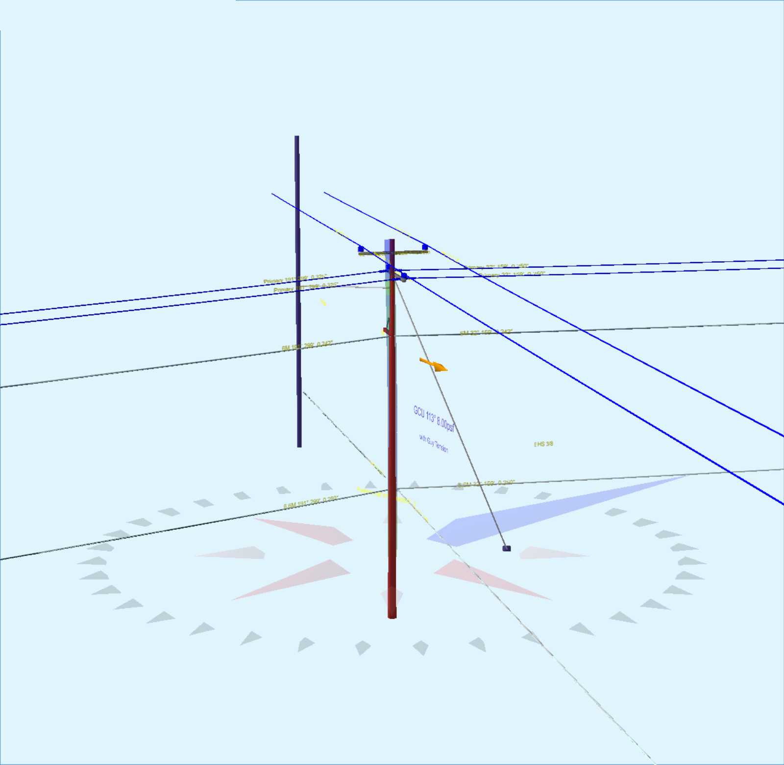
Explore selected work in pole loading, mechanical design, and small-cell modeling. View each dedicated portfolio or download its PDF.

Explore our portfolios

Three portfolios.
One engineering team.

Explore selected technical work in pole loading, mechanical design, and small-cell equipment modeling, with dedicated portfolios available online and in PDF.

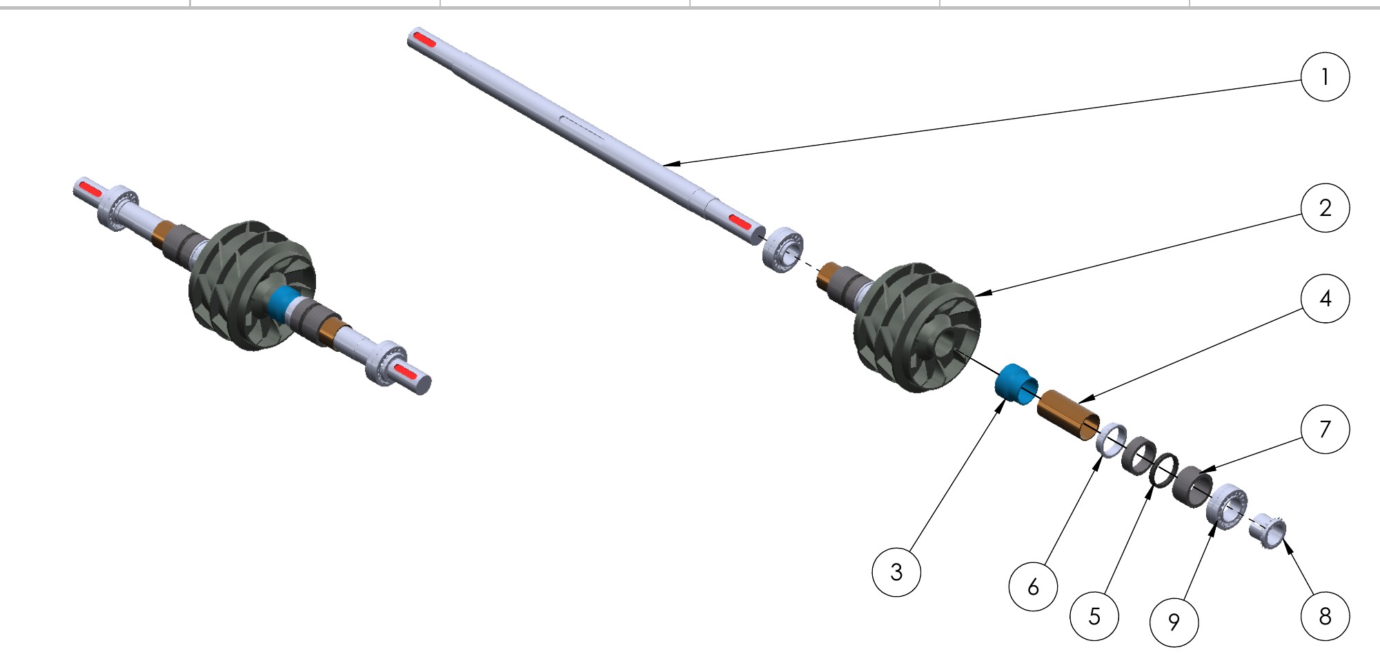
Exploded mechanical assembly showing individual components and their arrangement02 / MECHANICAL DESIGN
SOLIDWORKS / FABRICATION DRAFTING

From geometry to fabrication.

Part and assembly modeling, sheet metal enclosures, steel frames, equipment layouts, and detailed technical drawings. A closer look at component relationships and fabrication detail.

SolidWorks3D assembliesFabrication drawings
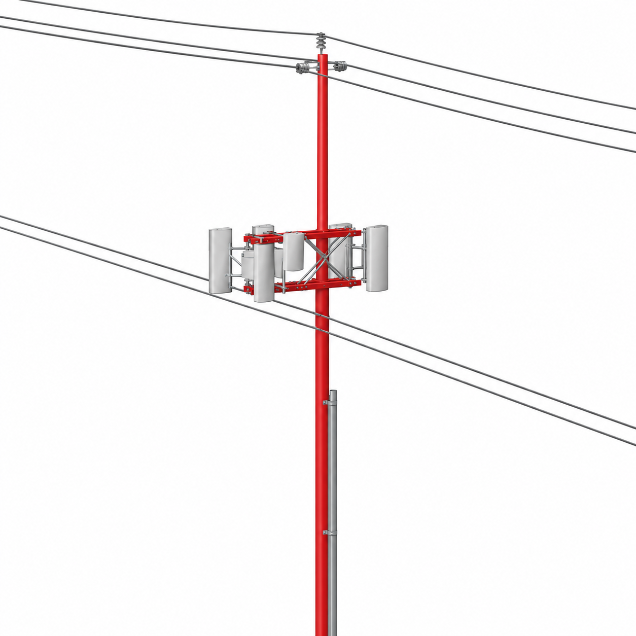
Small-cell equipment assembly with mounting frame and overhead utility attachments03 / SMALL CELL ENGINEERING
O-CALC PRO / SMALL CELL

Equipment detail. Drawing alignment.

Small-cell equipment modeling coordinated with reference drawings, mounting details, and manufacturer data. Review dimensions, weight, height, offset, orientation, and the loads transferred to the pole.

Equipment inputsMounting geometryLoad-path review

Selected work is presented with project identifiers and original client title blocks removed.

Selected engineering work

Experience you can see.
Detail you can review.

A selection of modeling and drafting excerpts from our supplied work portfolio, spanning mechanical equipment, fabrication, and infrastructure documentation.

MECHANICAL / ASSEMBLY

Parts that work together.

Exploded and assembled views communicate component relationships and assembly arrangement.

EQUIPMENT / THERMAL

Equipment, clearly documented.

Coordinated views show coil routing, connection geometry, and equipment supports.

FABRICATION / SHEET METAL

From panels to a complete form.

Enclosure modeling brings together openings, panel geometry, and exploded component views.

FABRICATION / STEEL FRAMES

Structure through detail.

Assembly and frame documentation communicates bracing, access, and component connections.

PROCESS / EQUIPMENT LAYOUT

A view of the bigger picture.

Equipment placement and piping relationships presented within a coordinated 3D environment.

UTILITY / STRUCTURES

Infrastructure, connected.

Conceptual CAD-style line drawing shows a utility structure and selected connection details. Not to scale or for construction.

Explore the SolidWorks selection.

More assembly views, fabrication details, and technical drawing excerpts.

Selected drawing excerpts are presented without original client title blocks. Source drawing annotations retain their original language and units.

Start a conversation

Let’s start with your requirements.

Share sample inputs and expected deliverables so we can define the scope, approach, and delivery schedule.

YOUR PROJECT AT A GLANCE
Service neededSample inputsDeliverable formatsWork volumeTarget schedule